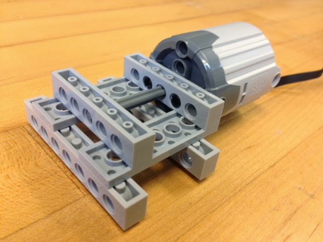
Since the MicroLogix 1100 has only 10 inputs and 6 outputs, why not design something for it? what about an elevator? So, this post will be an elevator setup for a three story building. We will be using LEGO Mindstorms because we have a few around, but you can design another model.
Outputs (4 for now): motor up, motor down, up lights and down lights. You may add a motor to open/close the elevator doors. Inputs (10): three sensors for floor level sensing, three floor selection buttons (the ones inside the elevator), and four buttons for calling the elevator (the ones outside the elevator) For now, just the pics: |
Debido a que el MicroLogix 1100 tiene solo 10 entradas y 6 salidas, ¿Por qué no diseñar algo con ello en mente? ¿Qué tal un elevador? Este entrada es para un elevator de tres pisos. Usaremos LEGO Mindstorms porque lo tenemos disponible, pero puedes otro estilo.
Salidas (4 for ahora): subir y bajar para el motor, luces que indican si sube o baja. Puedes añadir otro motor para abrir y cerrar las puertas del elevador. Entradas (10): tres sensores para detectar en que piso está, los tres botones de dentro del elevador, y 4 botones fuera del elevador. Por ahora, solo las fotos: |
 |
 |
 |
 |
 |
 |
 |
 |
 |
 |
 |
 |
 |
 |
 |
 |
 |
|
| You need to add the sensors for the floor level: to determine where the elevator is, 1st, 2nd or 3rd floor (I don't have a pic of that one!). You may have to use the best switch you can find for the job. You also need the control panel: the buttons and lights. The three buttons inside the elevator and the four buttons outside (one on the 1st floor to go up, one on the third floor to go down, and two for the middle floor to go up and down). |
Tienes que añadir los sensores de nivel: para determinar en que piso está el elevador, el 1ro, 2do o 3ro (No tengo esa foto!). Es probable que tengas que buscar el mejor interruptor que sirva para ese trabajo. También hace falta el panel de control: los botones y las luces. Son los tres botones dentro del elevador y los cuatro fuera de el (uno en el 1ro para subir, uno en el último para bajar, y dos en la mitad para subir y bajar). |
.JPG) La tarjeta del panel de control |
.JPG) La tarjeta del panel de control |
Tuesday, September 16, 2014
PLC Elevator
Sunday, September 14, 2014
PLC Lights and Switches
| The next challenge will use the board on the image below. There are several options with this one. You can use the lights on the right or the traffic lights. This board has 2 push-buttons (normally open) and two switches with two positions (two outputs per switch) for a maximum of six inputs. The third generation of this board has 5 different switches for a maximum of 9 inputs. There are six LED lights on the right and the wiring for the traffic light also was designed for also controlling 6 outputs (2 green lights, 2 red, lights and 2 yellow lights). |
El siguiente desafio usará la tarjeta de la imagen de abajo. Hay varias opciones con esta tarjeta: puedes usar las luces de la derecha o las del semáforo. Esta tarjeta tiene dos pulsadores (normalmente abiertos) y dos interruptores de doble posición (dos salidas por interruptor) para un máximo de 6 salidas. La tercera generación de esta tarjeta tiene 5 interruptores diferentes para un máximo de 9 salidas. Hay 6 luces LED en la derecha y el cableado del semáforo está diseñado para controlar también 6 luces (2 rojas, 2 verdes y 2 amarillas). |
The board will be used for two tasks:
|
La tarjeta será usada para dos tareas:
|

The Lights & Switches board / La tarjeta de Luces e Interruptores
|
|
1st part of the challenge (warming up):
2nd part of the challenge (still warming up):
3rd part "The Challenge": The program should be able to make the 1st part and the 2nd part of the challenge but on the same code: without the coding for the switches of the first part affecting the running lights code. The should run as if they were individual. |
Primera parte del desafío (calentamiento):
2da parte del desafío (aun calentando):
3ra parte "El Desafío": El programa ahora debe de correr la 1a y 2da parte del desafío en el mismo código sin que el código de la primera parte afecte al de las luces. Deben de correr como si fueran codigos independientes. |
After "The Challenge", you can start planning about the traffics light programming. |
Después de "El Desafío", puedes planificar acerca de la programación de las luces del semáforo. |
| If you design your own board, you may improvise as you see fit. My first board (photo below) was not a elegant an clean as the second generation. | Si diseñas tu propia tarjeta, tendrás que improvisar según sea necesario. Mi primera tarjeta (foto de arriba) no es tan elegante ni tan limpia como la de la segunda generación. |

First prototype board / Primer prototipo de tarjeta
|
|
Saturday, September 13, 2014
PLC Programming: 1
| First, I need to thank my students: Christian Barresi, Nellie Bonilla, Luis Flores and Amarilys Rivera for creating the first tutorial some time ago (2011). I hope to continue their initial work. Lets start with the programming language. The MicroLogix 1100 comes from a family of Allen-Bradley controllers made by Rockwell Automation which uses ladder logic. In summary it's called ladder because the program resembles a ladder. It's better to have a quick summary on ladder logic to understand it better. Wikipedia has a nice review to get you up to speed: http://en.wikipedia.org/wiki/Ladder_logic Below you will find the test electrical circuit and the program for it. |
Primero, tengo que dar gracias a mis estudiantes: Christian Barresi, Nellie Bonilla, Luis Flores y Amarlys Rivera por crear el primer tutorial hace ya algún tiempo (2011). Espero continuar su trabajo inicial. Comencemos con el lenguage de programación. El MicroLogix 1100 viene de una familia de controladores de Allen-Bradley fabricados por Rockwell Automation que utilizan el lenguage LADDER, escalera o de contactos. Se le conoce como escalera por la forma de los programas. Es mejor tener un sumario rápido del lenguage escalera para entenderlo. Wikipedia tiene un buen resumen para aprenderlo rápido: http://es.wikipedia.org/wiki/Lenguaje_Ladder Abajo se encuentra el circuito eléctrico de prueba y su programa. | ||||||||

Electrical diagram/Diagrama eléctrico
|

Ladder program / Programa en lenguaje escalera
|
||||||||
|
|
||||||||
 |
|
||||||||
| Get familiar with the options, practice dragging and dropping a few icons. Get the program to look like the one in the image. For the input you need to write I:0/0 so it looks like the figure (Input:zero/zero). For the output you need to write O:0/0 so it also looks like the one in the figure (Output:zero/zero). The last number dictates the physical connection on the PLC. | Familiarizate con las opciones, practicando arrastrar y soltar con algunos iconos. Escribe el programa para que luzca similar al de la imagen. Para la entrada es necesario escribir I:0/0 para que quede como en la imagen (Input:cero/cero). Para la salida hay que escribir O:0/0 para que también se parezca a la imagen (Output:cero/cero). El último número es el que indica la conexión física en el PLC. | ||||||||
| After that, you need to verify the program, the green check mark icon, for errors (writting zero instead of the letter O, colon, semicolon, period, etc). Once you are ready, you can transfer the program to the PLC, the option is called Download. |
Después de ello, hay que verificar el programa con el icono de la marca verde (verify) para posibles errores (un cero en vez de la letra O, dos puntos, punto y coma, puntos, etc). Una vez realizado, ya se puede transferir el programa al PLC, la opción se llama Download. | ||||||||
| You may need to change the Mode Switch option on the PLC to proceed (you need to use the ESC and OK buttons to navigate). Follow the on screen recomendations. Manual mode is Program and Run to be executed on the PLC. Remote mode allow you to program and run from the PC. Check image below. |
Puede que tengas que cambiar una la opción del Mode Switch en el PLC para continuar (hay que usar ESC y OK para navegar las opciones). Sigue las recomendaciones en pantalla. El modo manual permite programar (Program) y correr (Run) desde el PLC. El modo remoto permite programar y correr desde el PC. Ver imagen. |
||||||||
.JPG) |
 |
||||||||
Now, check your program: when you activate the switch the light gets turned on. |
Ahora a probar el programa: cuando activas el interruptor la luz se debe de enceder. |
||||||||
| Congratulations, you are done with your first PLC program! | Felicitaciones, has terminado tu primer programa en PLC! |
MicroLogix 1100 Wiring
| You should get a power line (bottom left corner) and network cable (top left corner), like the picture below. Depending on the specific model, the MicroLogix 1100 is powered by 12/24V dc or 120/240V ac. |
Deberías tener el cable de corriente (esquina inferior izquierda) y el cable de red (esquina superior izquierda), como en la foto.. Dependiendo del modelo en específico, el MicroLogix 1100 es alimentado por 12/24V dc o 120/240V ac. |
 |
|
| The MicroLogix 1100 has the 12 inputs located on the top and 6 outputs located at the bottom. Depending on the specific PLC model, you may have 10 digital inputs (12/24V dc or 120V ac) and 2 analog inputs (10V dc) with 6 relay outputs (or two relay outputs and four 24V FET dc outputs). The model we have available is 120V ac, with 10 digital inputs using 24V dc (and two 10V dc analog inputs) and 6 relays outputs. A relay is just an electrically operated switch. You can think the PLC senses the digital inputs like a multimeter, if it detects the voltage (24V dc for us) the input is activate. So, you need to connect your inputs to a power supply in order for them to work. You should find a built-in power supply for it on the top row to the left. You will find there is only one screw connector for each input. The outputs work a bit different since you need 2 screw connectors for every output. You also need to provide your own power supply for the outputs. The good thing is that you can connect 5V dc in one output, 12V dc in other, 24V dc in another, 120V ac in another one and/or 240V ac in yet another output without any problem. Those are independent of each other. Why? Because you can connect anything you need. |
El MicroLogix 1100 tiene 12 entradas en la parte superior y 6 salidas en la parte de abajo. Dependiendo del modelo de PLC, puedes tener 10 entradas digitales (12/24V dc o 120V ac) y 2 entradas análogas (10V dc)con 6 salidas con relés (o dos salidas con relés y cuatro con 24V FET dc). El modelo que tenemos disponible es de 120V ac, con 10 entradas digitales usando 24V dc (más dos entradas análogas de 10V dc) y 6 salidas de relés. Un relé no es más que un interruptor operado eléctricamente. Puedes pensar que el PLC detecta las entradas como si fuera un multímetro, si detecta el voltage (24V dc para el que tenemos) la entrada está activa. Las entradas necesitan estar conectadas a una fuente de poder para funcionar, para ello se puede usar la que viene con los conectores del lado izquierdo. Encontrarás un conector para cada entrada. Las salidas funcionan diferente porque tienes dos conectores para cada salida. Aquí se necesita proveer la fuente de poder para las salidas. Lo bueno de ello es que una salida puede estar a 5V dc, otra a 12V dc, otra más a 24V dc, otra a 120V ac y una última a 240V ac sin ningún problema. ¿Por qué? Porque así puedes conectar lo que necesites. |

Inputs on the top, outputs on the bottom
Entradas en la parte de arriba y salidas en la de abajo.
|
|
| Since the inputs require a power supply, we will use the one built-in. You need to place a jumper wire from -24V to the COM (common) connector to complete the electrical circuit. See the example below for the input zero (I/0). |
Ya que las entradas necesitan una fuente de poder, usaremos la que viene con el PLC. Hace falta un cableado del -24V a el puerto COM (común) para cerrar el circuito eléctrico. Ver el ejemplo de abajo para la entrada cero (I/0). |

One input connection/Una conexión de una entrada
|
|
| If you need more connections, make sure to place another jumper wire until the next COM port to be able to use the last 6 inputs. Check image below with 5 connected inputs. | Si necesitas más conexiones, asegurarse de colocar otro cableado hasta el siguiente puerto COM para usar las últimas 6 entradas. En la imagen de abajo hay 5 entradas conectadas. |

Multiple input connections/Conexiones con entradas múltiples.
|
|
| Inside the PLC: the outputs have relays to open/close circuits and control turning on/off the connected equipment. The image below is the idealized way of how they work (grey color switches for internal components). | Dentro del PLC: las salidas tienen relés para abrir/cerrar circuitos y controlar el encendido/apagado de los equipos conectados. La imagen de abajo es una forma idealizada de como trabajan (interruptores en color gris claro para los componentes internos) |

Internal relays for outputs behaves like switches
Relés interbos para las salidas se comportan como interruptores
| |
| Let's make a connection with one input and one output. The input can be a switch, a push-button or just a wire. The output can be a light and its power source. The circuit should look similar to the figure below. |
Hagamos una conexión con una entrada y una salida. La entrada puede ser un interruptor, un botón tipo pulsador o solo un cable. La salida puede ser una luz con su fuente de poder. El circuito debería ser similar al de abajo. |

Connection for one input and one output/Conexión para una entrada y una salida.
|
|
| The ladder logic program for this one should look like the image below. | La programación en lenguage escalera para este circuito debería ser similar a la imagen de abajo. |
La entrada cero activa la salida cero |
|
| Take care to label your electrical connections so you don't forget what is what. If you need to use all the inputs and outputs, the wiring will look intimidating. It would be better if you can have color cables or color ribbon cables to help you with this task. Otherwise, imagine a circuit like the one below with cables coming from everywhere while you try to discover the order of the connections. |
Ten cuidado de rotular las conexiones eléctricas para no olvidar que es cada cosa. Si tienes que usar todas las entradas y salidas, el cableado será intimidante. Sería bueno si puedes tener cables de colores o cable cinta de colores para ayudarte en esa tarea. Sino, imagina que tengas un circuito como el de abajo con cables que vienen de todos lados mientras intentas descubrir el orden de las conexiones. |

Multiple inputs and multiple outputs with the same power supply
Múltiples entradas y múltiples salidas con la misma fuente de poder
|
|
Monday, April 15, 2013
MicroLogix 1100 - Setup
Since I'll be using the MicroLogix 1100 in class (Mechanical Engineering), I think many would find this information helpful. I'll be using the Allen-Bradley MicroLogix 1100 because it is the one available.
Interestingly enough, software for programming it can be downloaded for free from the vendor (Rockwell Software).
PLCs are not inexpensive, they are industrial equipment for a reason, so prices can range from relatively economical to insanely expensive (from a student's viewpoint anyway). The complexity of the process is what guides this decision.
The MicroLogix 1100 is moderately priced (from about US $200 on ebay). The MicroLogix 1200 seems to be more bang for the buck (24 inputs, 16 outputs) against the 1100 (10 inputs, 6 outputs) among other perks. The 1000 model is another option, while the 1400 seems to be popular for industrial applications.
Anyway, from an educative standpoint, if you can afford it, go for it. However, when budget is a limitation, even free software can mold a decision.
Given that Rockwell Automation (company parent of Allen-Bradley) gives for free software for the MicroLogix 1000 and 1100. It makes it easier to decide.
What is needed?
Go to this link and download the RSLogix Micro Starter Lite and the RSLinx Lite. There is even an Emulator if you don't have the hardware (for MicroLogix 1000, 1100, 1200, 1400 and 1500).
Once you install them, there are 3 steps.
For Windows XP, Rockwell provides a nice straightforward tutorial for the configuration of BOOT-DHPC. You need a PC with a network, LAN or Ethernet port and a network cable as well for this step. The PC talks to the PLC using a network cable.
Configuring BOOTP-DHPC is not complicated for a desktop computer, but laptops...especially with Windows 7... requires a couple of extra steps.
Dr. Jeff Jackson from the Department of the Electrical and Computer Engineering of the University of Alabama already has a nice tutorial that you could use.
Anyway, I'll be posting my step-by-step instructions too.
First time you open the BOOTP-DHPC it will ask to configure the network settings. Choosing 255.255.255.0 for the Subnet Mask is enough. You can modify this value later.
From Wikipedia: BOOTP stands for Bootstrap protocol
(network protocol used by a network client to obtain an IP address from a configuration server). DHPC stands for Dynamic Host Configuration Protocol (advanced protocol for the same purpose and has superseded the use of BOOTP. Most DHCP servers also function as BOOTP servers).
|
Debido a que estaré usando el MicroLogix 1100 en clase (Ingeniería Mecánica), pienso que otros encontrarán útil esta información. Estaré usando el Allen-Bradley Micrologix 1100 porque es el que tenemos disponible.
De forma curiosa, el software para programarlo se puede descargar gratis desde la página del vendedor (Rockwell Software). Los PLCs no son económicos, por algo son equipos de uso industrial, los precios varian de moderadamente económicos a muy costosos (desde el punto de vista de un estudiante). La complejidad del proceso es quien dicta esta decisión. El MicroLogix 1100 es medianamente costoso (desde US $200 en ebay). El MicroLogix 1200 ofrece más por el precio (24 entradas, 16 salidas contra el 1100 (10 entradas, 6 salidas) entre otras cosas. El modelo 1000 es otra opción, mientras que el 1400 parece ser popular en aplicaciones industriales. Desde el punto de vista educativo, si lo puedes pagar, consíguelo. Sin embargo, cuando el presupuesto es una limitante, hasta el software gratis puede moldear una decisión. Ya que Rockell Automation (la companía matriz de Allen-Bradley) provee el software libre de costo para el Micrologix 1000 y 1100, hace la decisión fácil.
¿Que se necesita?
Ir a este enlace y descargar el RSLogix Micro Starter Lite y el RSLinx Lite. Inlcuso, hay un emulador si no tienes el equipo físico (para el MicroLogix 1000, 1100, 1200, 1400 y 1500).
Una vez instalado, son 3 pasoa a seguir:
Para Windows XP, Rockwell provee un tutorial para la configuración del BOOTP-DHCP. Se necesita para ello un PC con un puerto de red, LAN o Eternet y un cable de red. El PC se comunica con el PLC a través de un cable de red.
Configurar el BOOTP-DHCP no es complicado para un PC de escritorio, pero los portátiles... especialmente con Windows 7... requieren de pasos extra.
Dr. Jeff Jackson del Departamento de Ingeniería Eléctrica y Computadoras de la Universidad de Alabama tiene un buen tutorial que se puede usar.
De todas maneras estaré colocando las instrucciones detalladas.
La primera vez que se abre el BOOTP-DHCP se pide configurar la red. Escogiendo 255.255.255.0 para el Subnet Mask es suficiente. Estos valores también se pueden modificar luego.
De Wikipedia: BOOTP (Bootstrap Protocol) es un protocolo usado por clientes de red para obtener una dirección IP. El DHCP (protocolo de configuración dinánica de host), es un protocolo basado en BOOTP avanzado. Muchos servidores de DHCP también ofrecen soporte para BOOTP)
|

Network Settings recommended for BOOTP-DHCP Server
Configuración recomendada para el servidor de BOOTP-DHCP
|

BOOTP-DHCP Server window
Ventana del servidor de BOOTP-DHCP
|
IP Address Configuration
You need to configure an IP Address for the PLC based on the IP Address of the PC. Open a Command Prompt (cmd), write ipconfig and hit enter.
If you are using a desktop PC without a wireless network card, you should see an image similar to the one below, showing only the Ethernet configuration. You need to look for the IP Address (IPv4 Address).
If you have an IP address, you can skip this part and go to BOOTP-DHCP configuration section.
|
Configuración de la Dirección IP
Se necesita un adirección de IP para el PLC basado en la dirección de IP del PC. Abrir una ventana de comandos o "Command Prompt" (cmd) escribir ipconfig y dar enter. En una PC de escritorio sin tarjeta de red wireless, se puede ver una imagen similar a la de primera de abajo, que muestra la configuración de Ethernet. Hay que buscar la dirección IP (IPv4 Address). Si tienes la dirección de IP, puedes saltar esta parte e ir a la configuración del Servidor de BOOTP-DHCP. |

PC with only one network configuration
PC con una sóla configuración de red

PC with only one network connection
PC con usa sola configuración de red
|

Laptop with several network connections disabled
Portátil con varias conexiones de red deshabilitadas
|
If you are using a laptop, it is probable that you'll see several adapter configurations (Windows 7 may list several, my laptop shows 2 LAN connections when there is 1 port). You need to look for one that says Ethernet adapter Local Area Connection. If there are several connections, you might need to disconnect or disable the others (at least temprarily). If you don't see the IP Address, you will need to configure one.
So, go to Control Panel and open Network Connections. You may need to disable temporarily connections other than the LAN (the physical port)

Likely configuration for a laptop connected to a wireless network
Configuración probable de un portátil conectado a una red wireless
Windows 7:
Once you have disabled the other connections, you need to check and or set a fixed IP Address for your PC. Right click, and select Properties for your Local Area Connection (LAN), and look for Internet protocol version 4 (TCP/IPv4). Choose Properties again.
Once you are there, check if your PC has a fixed or dynamic (IP address set automatically). PCs in institutions might have a fixed IP, just record the number some place else. Most home PCs or laptops have this set dynamically.
If you could not locate an IP Address with the ipconfig option from above, it is likely you will have to setup one here. For this example, I set my IP Address to 192.168.2.2 and the Subnet Mask as 255.255.255.0.
Remember to undo any changes later on if you need connect to a LAN.
 |
Si estas usando un portátil, es probable que existan varias configuraciones (Windows 7 puede mostrar varias, mi portátil muestra 2 puertos de LAN cuando sólo hay 1). Hay que buscar por el que dice Ethernet adapter Local Area Connection. Si hay varias conexiones, puede que sea necesario desconectar o deshabilitar las otras (al menos de forma temporal). Si no ves una dirección de IP, es necesario configurar una.
Ir a Panel de Control y abrir Conexiones de Red. Puede que necesites desconectar de forma temporal las conexiones que no sean las del LAN (el puerto físico).

Laptop with wireless off and disabled connections except for the LAN port
Portátil con el wireless apagado y todas las conexiones deshabilitadas excepto por el LAN
Windows 7:
Una vez estén deshabilitadas las otras conexiones, es necesario verificar o configurar una dirección fija de IP del PC. Clic con el botón derecho y seleccionar Propiedades para el LAN, y verificar para el para el protocolo de la versión 4 (TCP/IPv4). Escoger Propiedades de nuevo.
Una vez allí, revisa si el PC tiene una dirección fija de IP o dinámica (Dirección de IP seleccionada de forma automática). PCs en instituciones pueden tener un IP fijo, apuntar ese número. PCs caseras o portátiles tienen esta opción de forma automática.
Si no se puede localizar una dirección de IP con la opción ipconfig de arriba, es probable que sea necesario configurar una. Para este ejemplo, seleccioné la dirección IP como 192.168.2.2 y el Subnet Mask como 255.255.255.0.
Recuerda deshacer cualquier cambio si necesitas conectarte al LAN.
 |
BOOTP-DHCP Server Configuration
Once you have the IP address of your PC, you need to configure one for the PLC. The IP address will be the same except for the last number, pick your number (it is 2 for my PC and will be 3 for the PLC).
On the BOOTP window, double click on the Ethernet Adress (MAC) of the PLC in the upper part of the window (Request History). You can also select it and hit the Add to Relation List button.
Once you have the New Entry window, it should register the Ethernet Address (MAC) of your PLC. Then, you need to type the IP Address for the PLC (192.168.2.3 in this example), and hit OK. This will assign the IP address to the PLC (remember, it should not be equal to the PLC, otherwise the PC will try to talk with the PC!, and that's not the plan).
After a while, the BOOTP-DHCP Server will read the assigned IP Address on the upper part (Request History). After a minute or two, the IP address must appear on the PLC display under Ethernet Configuration (Advance Set > ENET Cfg). You need to check to be sure, otherwise the communication channel is not established yet.
|
Configuración del Servidor de BOOTP-DHCP
Una vez se tiene la dirección de IP del PC, es necesario configurar una par el PLC. La dirección de IP será idéntica excepto por la última cifra, escoge un número (es 2 para el PC y será 3 para el PLC). En la ventana del BOOTP, doble clic sobre la Ethernet Adress (MAC) del PLC en la parte de arriba (Request History). También se puede seleccionar y hacer clic en el botón de Add to Relation List. Una vez que tengas la ventana New Entry, debe mostrar el Ethernet Address (MAC) del PLC. Hay que escribir la dirección IP para el PLC (192.168.2.3 en el ejemplo) y click en OK. Esto asigna la dirección IP al PLC (recordar que la dirección no debe ser idéntica a la del PC, de lo contrario el PC intentará hablar con el PC, y ese no es el plan). Después de un rato, el servidor de BOOTP-DHCP mostrará la dirección asignada en la parte superior (Request History). Después de un minuto o dos, la dirección IP debe de aparecer en la pantalla PLC bajo la Configuración de Ethernet (Advance Set > ENET Cfg). Hay que revisar, de lo contrario la comunicación aún no está establecida. |

Configuriation the IP Address for the PLC
Configuración de la dirección IP del PLC
|
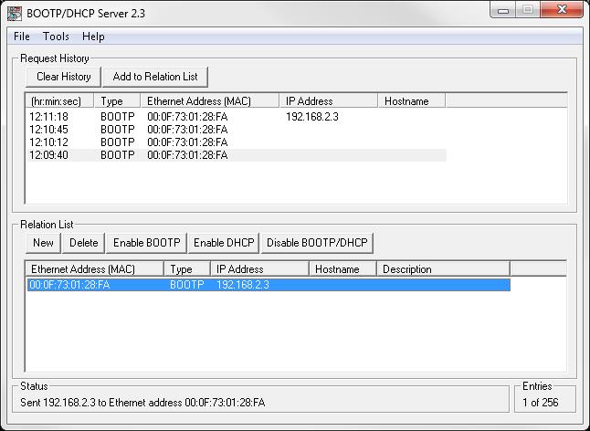
The assigned IP Address appears registered on top
La dirección IP asignada aparece registrada arriba
|

PLC without assigned IP Address
PLC sin dirección IP asignada
|

PLC with assigned IP Address by BOOTP-DHCP
PLC con dirección IP asignada con el BOOTP-DHCP
|
If you see an IP address on the PLC display, you are ready to configure the drivers and start programming.
You can save this configuration for next time (only double click on the saved file when closing this program). If you follow the instructions from Rockwell, you can set a fixed IP Address when you hit the Disable BOOTP/DHCP button. However, you will need to use RSLinx Classic to deselect that feature in case you need to setup another IP Address.
If you choose Disable BOOTP/DHCP, you will not be able to use BOOTP-DHCP if you want to change the IP Address until after you configure this using RSLinx Classic.
So, if the IP Address of the PC doesn't change or if it is for a fixed application (like industry), you want the IP Address fixed. Otherwise, when you power down the PLC this will be reset and you will need to configure again the IP Address. Which is a good experience for classes or if you own a laptop.
If you don't see it, you'll need to check if the computer IP Address is set statically and there are no other network connections enabled. Try power cycle (disconnect and connect the PLC power supply) and assign again the IP Address.
Once you are done, it is preferable to close the window, don't save a file, and don't choose the Disable BOOTP/DHCP button. Anyway, you need to read above first.
|
Si ves la dirección IP en la pantall del PLC, estás listo para configurar los drivers y comenzar a programar.
Esta configuración puede ser salvada para la próxima vez (haciendo doble clic en el archivo salvado cuando se cierra el programa). Si se siguen las instrucciones de Rockwell, se puede asignar una dirección fija de IP cuando se activa el botón de Disable BOOTP/DHCP. Sin embargo, hace falta usar RSLinx Classic para deshabilitar esa opción en caso de necesitar configurar otra dirección de IP.
Es decir, el activar Disable BOOTP/DHCP no permite volver a usar el BOOTP-DHCP para cambiar la dirección de IP hasta después de configurarlo en el RSLinx Classic.
Entonces, si la dirección de IP del PC no cambia o es para una aplicación fija (como en industria), es conveniente dejar la dirección IP fija. De lo contrario, cuando se desconecta el PLC de la corriente, esto borra esa asignación y es necesario configurar de nuevo la dirección de IP. Lo cual es una buena experiencia para clases o si tienes un portátil.
Si no aparece, hay que revisar si la dirección IP del computador está configurada estática y que no hallan más conexiones de red habilitadas. Intenta conectar y desconectar la corriente del PLC y asignar nuevamente la dirección IP.
Una vez termines, es preferible cerrar la ventana, no salvar archivos y no escoger el botón de Disable BOOTP/DHCP. De todas maneras, es necesario leer lo que está arriba.
|
Driver Configuration
Open RSLinx Classic Lite, it will appear only as RSLinx Classic. Go to the Communications menu and select Configure Drivers.
|
Configuración de los Drivers
Abrir RSLinx Classic Lite, aparece como RSLinx Classic. Ir al menú de Communications y selecciona Configure Drivers.
|
 |
 |
From the drop-down menu on Available Driver Types, choose EtherNet/IP Driver (it is an ethernet connection with an IP address for a reason). You can leave the default name or choose one on the Add New RSLinx Classic Driver window.
|
En el menú desplegable en Available Driver Types, escoger EtherNet/IP Driver (por algo la configuración de eternet y una dirección de IP). Puedes dejar el nombre por defecto o escoger uno en la ventana de Add New RSLinx Classic Driver.
|
 |
 |
Make sure you select the controller with the PC IP Address (192.168.2.2 for this example). You might see others depending on your network connections or if you enabled the network connections that were disabled.
Once you hit OK, you need to make sure that the Configured Drivers list has an status of Running. Otherwise, you need to hit Start. See example below.
Drivers are already configured for the IP Address selected. If you change the PC IP Address, you'll need to repeat this step.
|
Asegurarse que se seleccione el controlador con la dirección IP del PC (192.168.2.2 para este ejemplo). Puede que aparezcan otras conexiones de red o si se habilitaron conexiones que estaban deshabilitadas.
Una vez que se da OK, hay que verificar que en la lista de Configured Drivers aparece con un estado de Running. De lo contrario, es necesario dar Start. Ver las imágenes de abajo.
Los drivers ya están configurados para la dirección de IP seleccionada. Si la dirección de IP del PC cambia, es necesario repetir este paso.
|
 |
 |
You need to verify everything is running smoothly. Go to Communications, select RSWho, and under the Ethernet Driver tree, you must see the IP adress assigned to the PLC as connected. You can close this program.
Finally you are ready to start programming.
|
Hace falta verificar que todo corre como debería. Ir a Communications, seleccionar RSWho, y bajo el menú de del driver de Ethernet, debe de aparecer la dirección IP asignada al PLC como conectado. Puedes cerrar este programa.
Finalmente ya está todo listo para empezar a programar.
|
 |
 |
How To Start Programming
Open RSLogix Micro Starter Lite. You can open a New File and choose from the menu the right configuration, or go to the Comms Menu, and select the option Who Active Go Online. You should be able to see the device with the IP Address you configured earlier.
Choose the PLC IP Address and hit Create New File. It will pick up the right processor information for the PLC connected, or you can do it manually from the New File menu.
|
Como empezar a programar Abrir RSLogix Micro Starter Lite. Puedes abrir un archivo nuevo en el menú de New File y escoger la configuración correcta, o puedes ir al menú de Comms y seleccionar la opción de Who Active Go Online. Debería ver el equipo configurado con la dirección IP.
Escoger la dirección IP del PLC y seleccionar Create New File. Esto configura la informacion correcta del procesador para el PLC que est;a conectado. También se puede hacer de forma manual desde el menú de New File.
|
 |
 |
|
 |
The first time it runs it will load whatever is saved on the PLC memory. See below. If you want to start programming, you need to select OFFLINE from the first drop down menu on the left. Follow the instructions, until you see a window similar to one on the bottom right. So, you are ready to start programming. |
La primera vez que el programa corre va a cargar lo que estaba en la memoria del PLC. Imagen de abajo a la izquierda. Si quieres programar, es necesario seleccionar OFFLINE en el menú desplegable de la izquierda. Seguir las instrucciones hasta tener una ventana similar a la de abajo. Finalmente, ya estas listo para empezar a programar. |
|
|
Subscribe to:
Posts (Atom)